 |
|
|
|
||||||||||||||||


 톡톡
톡톡- > 전자키트
- > 프로세서/개발보드
- > Arduino(아두이노)
- > Arduino
- 공식 아두이노팀에서 제조한 전원 관리 IC 개발 도구 ARDUINO MOTOR SHIELD REV 3
-
A000079 아두이노 모터쉴드 R3 (Arduino Motor Shield Rev3)
상품번호 : 10868
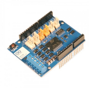


아두이노 모터 쉴드는 L298을 기반으로 만들어졌습니다.
L298은 릴레이나 솔레노이드, DC모터와 스테핑 모터와 같은 유도부하를 구동하도록 설계된 듀얼-브릿지 드라이버입니다.
이 쉴드를 이용하면, 아두이노를 이용해서 2개의 DC모터를 구동할 수 있습니다. 각각의 모터의 속도와 방향을 독립적으로 제어할 수 있고, 각 모터의 전류 소모량도 측정할 수 있습니다. 또한 TinkerKit 호환의 컨넥터를 제공하기 때문에,TinkerKit모듈을 이용하거나, 또는 자신만의 모듈을 만들어 이 쉴드에 플러그를 꼽는 방식으로 이용할 수도 있습니다.
이 쉴드는 2개의 분리된 채널을 가지고 있습니다. 채널A와 채널B로 불리는데, 각 채널마다 각각 4개의 Arduino 핀을 사용 하며, 이것들로 방향전환, 속도조절, 급정지, 소모전류측정을 할 수 있습니다. 이 쉴드를 통해 총 8개의 핀을 사용하는 셈입니다. 2개의 채널을 독립적으로 사용하면 2개의 DC모터를 구동할 수 있고, 채널A와 채널B를 함께 사용하면 1개의 바이폴라 스테핑모터를 구동할 수 있습니다. 이 쉴드는 각 채널 당 2A, 둘을 합해 최대 총 4A의 전류를 공급할 수 있습니다.
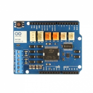
아두이노 모터 쉴드는 1.0 표준 핀아웃으로 설계되었습니다. Arduino Uno R3외 정확히 같은 핀배열을 가지고 있습니다.
http://arduino.cc/en/Main/ArduinoMotorShieldR3
Overview
The Arduino Motor Shield is based on the L298 (datasheet), which is a dual full-bridge driver designed to drive inductive loads such as relays, solenoids, DC and stepping motors. It lets you drive two DC motors with your Arduino board, controlling the speed and direction of each one independently. You can also measure the motor current absorption of each motor, among other features. The shield is TinkerKit compatible, which means you can quickly create projects by plugging TinkerKit modules to the board.
Summary
| Operating Voltage | 5V to 12V |
| Motor controller | L298P, Drives 2 DC motors or 1 stepper motor |
| Max current | 2A per channel or 4A max (with external power supply) |
| Current sensing | 1.65V/A |
| Free running stop and brake function |
Schematic & Reference Design
EAGLE files: arduino_MotorShield_Rev3-reference-design.zip
Schematic: arduino_MotorShield_Rev3-schematic.pdf
Power
The Arduino Motor Shield must be powered only by an external power supply. Because the L298 IC mounted on the shield has two separate power connections, one for the logic and one for the motor supply driver. The required motor current often exceeds the maximum USB current rating.
External (non-USB) power can come either from an AC-to-DC adapter (wall-wart) or battery. The adapter can be connected by plugging a 2.1mm center-positive plug into the Arduino's board power jack on which the motor shield is mounted or by connecting the wires that lead the power supply to the Vin and GND screw terminals, taking care to respect the polarities.
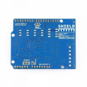
To avoid possible damage to the Arduino board on which the shield is mounted, we reccomend using an external power supply that provides a voltage between 7 and 12V. If your motor require more than 9V we recommend that you separate the power lines of the shield and the Arduino board on which the shield is mounted. This is possible by cutting the "Vin Connect" jumper placed on the back side of the shield. The absolute limit for the Vin at the screw terminals is 18V.
The power pins are as follows:
- Vin on the screw terminal block, is the input voltage to the motor connected to the shield. An external power supply connected to this pin also provide power to the Arduino board on which is mounted. By cutting the "Vin Connect" jumper you make this a dedicated power line for the motor.
- GND Ground on the screw terminal block.
The shield can supply 2 amperes per channel, for a total of 4 amperes maximum.
Input and Output
This shield has two separate channels, called A and B, that each use 4 of the Arduino pins to drive or sense the motor. In total there are 8 pins in use on this shield. You can use each channel separately to drive two DC motors or combine them to drive one unipolar stepper motor.
The shield's pins, divided by channel are shown in the table below:
| Function | pins per Ch. A | pins per Ch. B |
| Direction | D12 | D13 |
| PWM | D3 | D11 |
| Brake | D9 | D8 |
| Current Sensing | A0 | A1 |
If you don't need the Brake and the Current Sensing and you also need more pins for your application you can disable this features by cutting the respective jumpers on the back side of the shield.
The additional sockets on the shield are described as follow:
- Screw terminal to connect the motors and their power supply.
- 2 TinkerKit connectors for two Analog Inputs (in white), connected to A2 and A3.
- 2 TinkerKit connectors for two Aanlog Outputs (in orange in the middle), connected to PWM outputs on pins D5 and D6.
- 2 TinkerKit connectors for the TWI interface (in white with 4 pins), one for input and the other one for output.
Motors connections
Brushed DC motor. You can drive two Brushed DC motors by connecting the two wires of each one in the (+) and (-) screw terminals for each channel A and B. In this way you can control its direction by setting HIGH or LOW theDIR A and DIR B pins, you can control the speed by varying the PWM A and PWM B duty cycle values. The Brake A and Brake B pins, if set HIGH, will effectively brake the DC motors rather than let them slow down by cutting the power. You can measure the current going through the DC motor by reading the SNS0 and SNS1 pins. On each channel will be a voltage proportional to the measured current, which can be read as a normal analog input, through the function analogRead() on the analog input A0 and A1. For your convenience it is calibrated to be 3.3V when the channel is delivering its maximum possible current, that is 2A.
Physical Characteristics
The maximum length and width of the Motor Shield PCB are 2.7 and 2.1 inches respectively. Four screw holes allow the board to be attached to a surface or case. Note that the distance between digital pins 7 and 8 is 160 mil (0.16"), not an even multiple of the 100 mil spacing of the other pins.
2. 해외구매 특성상 주문에서 배송까지는 평균 10~15일이 소요됩니다. 간혹 현지 제품 수급에 따라 부득이하게 시일이 더 소요 될 수 있으니 구매시 좀 더 여유있게 주문하시길 권합니다.
3. 해외 내수품인 관계로 A/S에 대해서는 별도의 책임을 지지 않습니다.
4. 해외배송 특성상 주문접수후 배송상태가 배송준비중으로 넘어간 경우 해외에서 국내로의 배송이 이루어지고 있다는 뜻입니다. 따라서 배송준비중으로 배송상태가 넘어간 경우 취소및 반품이 불가하므로 이점 양해 부탁드립니다.
5. 타 해외구매대행 사이트에서 주문하신 물건과 주문날짜가 겹치지않도록 주의해 주십시오. 통관날짜가 같을 경우 합산관세가 부가되게 됩니다.
|